


Cosmetic defects are a persistent challenge in plastic injection molding, and few are more common than flow lines. These subtle imperfections on a part’s surface can compromise its aesthetic quality, leading to costly rejections, production delays, and client dissatisfaction. Understanding the root causes of flow lines in injection molding is the first step toward achieving flawless, high-quality components consistently.
This article serves as an expert guide to diagnosing the causes of flow lines. We will explore the key factors—from material selection to mold design—and provide a clear, systematic framework for their prevention and resolution, ensuring your final product meets the highest standards.
Core Causes of Flow Lines
Contents
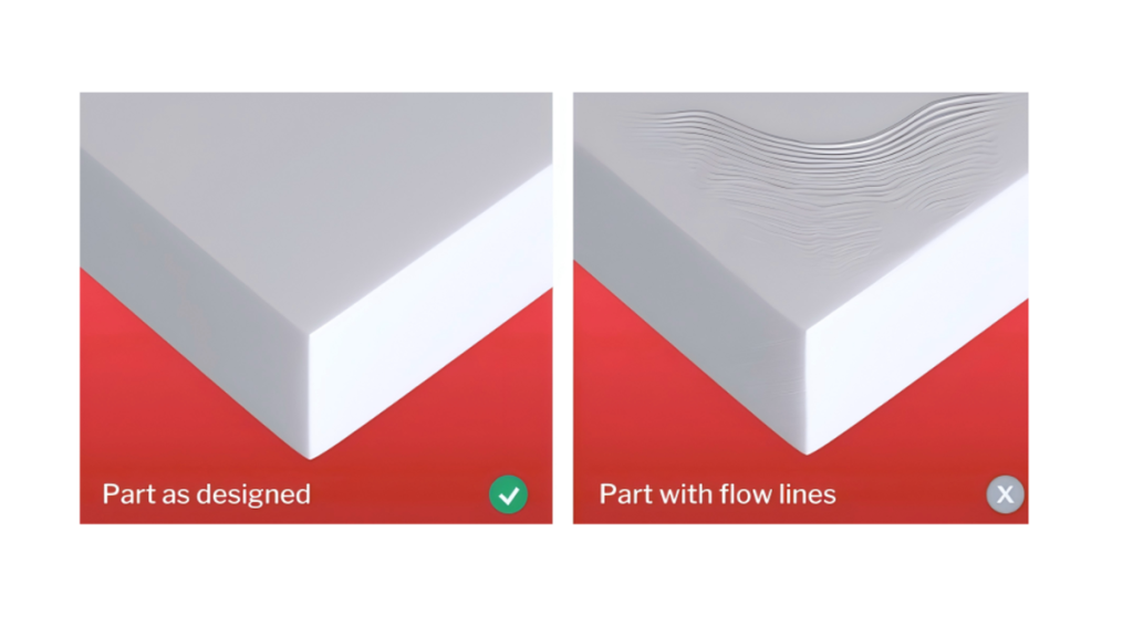
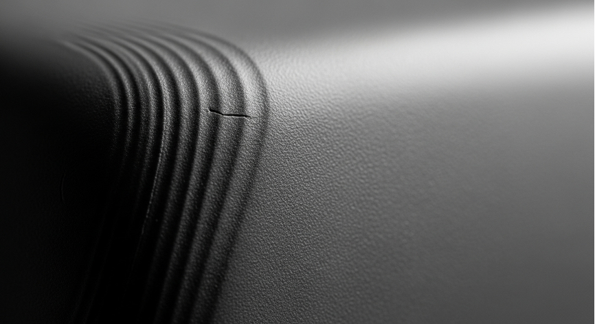
Flow lines (often used interchangeably with flow marks) are visible patterns, streaks, or ripples on the surface of a molded part. They typically appear as a wavy pattern, often radiating out from the mold’s entry point or “gate.” While they are not usually a structural concern, they are a clear indicator of a non-optimal molding process.
The governing principle behind all flow lines is the non-uniform cooling rate of molten plastic as it flows through and fills the mold cavity. When sections of the plastic cool and solidify at different speeds, their flow rates change, creating the visible lines where these sections meet. Several key factors contribute to this issue.
1. Material
The properties of the plastic resin itself are a primary variable.
- Low Melt Flow Index (MFI): Materials with a low MFI are more viscous (thicker) and resist flow. They require higher pressure and temperature to fill the mold properly. If the process isn’t perfectly optimized for this high viscosity, the material can cool prematurely, leading directly to flow lines.
- Improper Melt Temperature: Every material has an ideal temperature range. If the melt is too cold, its viscosity increases, hindering flow. If it’s too hot, the material can begin to degrade, altering its chemical structure and flow characteristics, which can also cause surface defects.
- Insufficient Drying: Many engineering plastics are hygroscopic, meaning they absorb moisture from the air. If not dried properly before molding, this trapped moisture turns to steam in the hot barrel, causing splay and disrupting the smooth flow of the molten plastic.
2. Machine & Process
The settings on the injection molding machine dictate the physics of the fill.
- Low Injection Speed or Pressure: Speed and pressure are critical for filling the mold cavity before the plastic has a chance to cool. If the injection speed or pressure is too low, the flow front of the plastic will begin to solidify before the mold is completely filled, creating drag and resulting inflow lines.
- Short Cycle Times: An overly aggressive cycle time may not allow for sufficient holding pressure (packing) or in-mold cooling. This can lead to variations in density and cooling as the part is ejected prematurely.
- Incorrect Nozzle/Barrel Temperatures: The barrel of the machine has several heating zones. A temperature profile that is too low or not properly graduated will fail to bring the material to a uniform, homogenous melt, causing viscosity variations within the plastic shot itself.
3. Mold Design
Often, the root cause of flow lines is engineered into the tool itself.
- Sharp Corners: Molten plastic flows like a fluid. Sharp internal corners in a mold cavity disrupt this smooth, laminar flow, creating turbulence and pressure drops that can cause the material to cool unevenly.
- Non-Uniform Wall Thickness: Drastic changes in wall thickness are a major cause of defects. The thicker sections take much longer to cool than the thin sections. This differential cooling creates internal stresses and disrupts the flow front as it moves from thin to thick areas.
- Small Gates and Runners: The gate is the entry point into the cavity, and runners are the channels that lead to it. If these are too small, they act as chokepoints. This restricts flow, causes a significant pressure drop, and can increase shear heat, potentially degrading the material—all of which contribute to the formation of flow lines.
- Poor Venting: As plastic enters the mold, the air inside must escape. If vents are too small, poorly placed, or clogged, trapped air gets compressed, creating backpressure that resists the plastic flow and can cause burn marks and incomplete fills (injection molding knit lines can also be worsened by this). This resistance directly impacts the uniformity of the flow.
Systematic Solutions for Prevention
Preventing flow lines requires a holistic and systematic approach. Simply changing one parameter may not solve the problem and can sometimes create another.
1. Process Parameter Adjustments
- Increase Injection Pressure and Speed: This is often the first and most effective adjustment. A faster, more forceful injection ensures the mold cavity is filled rapidly and completely before any part of the flow front can prematurely solidify.
- Optimize Temperatures: Ensure the barrel, nozzle, and even the mold temperatures are within the material manufacturer’s recommended range. A slightly higher mold temperature can keep the material molten for longer, improving the weld between flow fronts and reducing the appearance of flow lines.
- Adjust Holding Pressure and Time: After the initial fill, holding pressure (or packing) compensates for material shrinkage as it cools. Optimizing this can improve surface replication and minimize defects.
2. Mold Design Optimization
- Enlarge Gates and Runners: Widening these channels reduces pressure loss and allows the molten plastic to flow into the cavity more freely and uniformly.
- Incorporate Fillets and Rounded Corners: Replacing sharp internal corners with smooth, rounded transitions promotes laminar flow, preventing turbulence and pressure drops.
- Ensure Uniform Wall Thickness: The ideal design has a completely uniform wall thickness. Where this isn’t possible, transitions should be gradual and smooth, not abrupt.
- Improve Venting and Add a Cold Slug Well: Add or enlarge vents at the last point of fill to allow trapped air to escape easily. A cold slug well at the end of the runner system traps the colder, more viscous material at the leading edge of the melt, preventing it from entering the cavity and disrupting flow.
3. Material Selection
- Choose a Material with a Higher MFI: If the part design allows, selecting a resin grade with a higher Melt Flow Index (an “easier flow” material) can solve the problem with no other changes needed.
- Ensure Proper Material Handling: Strictly adhere to the manufacturer’s guidelines for drying time and temperature to eliminate moisture-related issues.
The HordRT Advantage: A Proactive Partnership
While the solutions above are effective reactive measures, leading injection molding providers emphasize a strategy of proactive prevention. Companies like HordRT function as strategic partners, integrating their expertise early in the process to guarantee quality and efficiency by solving problems before they happen. This approach is typically built on three core services:
- Design for Manufacturability (DFM): A core philosophy of this proactive model is DFM. Before any steel is cut for a mold, experts analyze the client’s part design. This critical step identifies and helps eliminate risks known to cause flow lines, such as sharp corners, problematic wall sections, or poor gate locations. The provider then delivers clear, actionable feedback to optimize the design for flawless, efficient manufacturing.
- Mold Flow Analysis: Advanced simulation software is utilized to create a virtual model of the injection process. This allows engineers to visualize precisely how plastic will fill the mold, predict potential flow lines, trapped air, and weld lines, and perfect the mold design accordingly. This data-driven approach eliminates guesswork and prevents costly tooling modifications down the line.
- Expert Consultation: The process is guided by a team of experienced engineers who work directly with the client. The goal is not just to present data, but to translate it into practical solutions. By combining advanced technology with decades of hands-on experience, every aspect of the project—from material selection to process control—is optimized for a perfect result.
Conclusion
Flow lines are a common but entirely preventable defect in injection molding. A successful outcome depends on a systematic approach that balances part design, material science, and process control. By understanding the core causes and implementing targeted solutions, it’s possible to achieve parts with impeccable surface quality.
If you aim for flawless components and want to leverage expert analysis to de-risk your next project, contact the HordRT team today.